Check, Directional and Flow Restrictor Functions
Cartridge valves for directional and check functions are essentially hydraulically piloted check valves. Control options include single or multiple pilot arrangements, flow restrictors, and solenoid controlled, pilot operated directional control. Grouping cartridge assemblies (selected individually according to flow requirements) for control by one or more common pilot valves can provide directional, check and/or flow restrictor functions for normal flow rates up to 3650 L/min (965 USgpm) per cartridge. Others provide flow restrictions between ports A and B and internal pilot orificing between port A and spring chamber AP. Poppets can be combined with different springs to provide three different cracking pressures.
Pressure Ratings
Maximum pressure allowable at ports A and B is 350 bar (5000 psi) for all cartridges. Minimum pressure is 0,3 to 5 bar (4.4 to 72 psi), dependent on the poppet/spring combination. The maximum pressure limit at pilot ports X, Z1, Z2 and AP and pilot valve interface ports P, T, A and B is generally 350 bar (5000 psi), dependent on the limit of any associated pilot valve or module.
Pilot port Y maximum pressure limit is also 350 bar (5000 psi). However, port Y is normally used as the pilot drain port, when it should be connected directly to the reservoir. In many functions any pressure at port Y is additive to the set opening/cracking pressure of the cartridge.
Remote Pilot Operated Functions
Remote piloted arrangements (pilot not integrally mounted on cartridge cover) require the application of pilot flows and pressures appropriate to the application and within the limits of any associated pilot valves and modules, whichever have the lower limits.
Solenoid Operated, Hydraulically Piloted Arrangements
For full technical data of pilot valves see appropriate Danfoss-Vickers catalog.
| Nominal Size ISO 7368 (DIN 24342) | Nominal flow at Δ p = 1 bar L/min | USgpm | Nominal flow at Δ p = 5 bar L/min | USgpm |
| 06 (NG16) | 128 | 34 | 255 | 67 |
| 08 (NG25) | 250 | 66 | 590 | 155 |
| 09 (NG32) | 300 | 80 | 1250 | 330 |
| 10 (NG40) | 500 | 132 | 1700 | 450 |
| 11 (NG50) | 850 | 225 | 2350 | 620 |
| 12 (NG63) | 1400 | 370 | 3650 | 965 |
Check Valve Functions
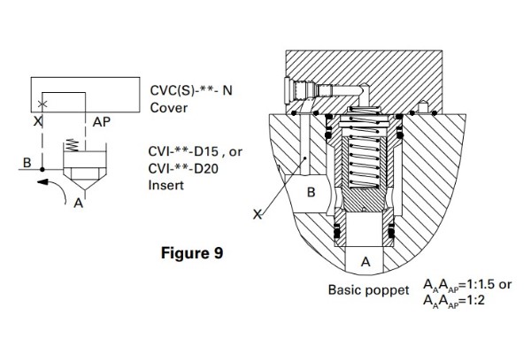
Basic Check Valve: Sizes 16 to 63
The standard directional cover (model code letter N), contains a pilot pressure passage with an orifice to control the poppet’s opening and closing rate. When used with insert model D15 (1:1.5 area ratio poppet), or model D20 (1:2 area ratio poppet), the combined cover and insert, Figure 9, becomes a check valve. Port X in the cover is connected to port B in the insert. This allows free flow from insert port A to port B while blocking flow from B to A.
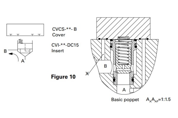
Direct Acting Check: Sizes 16 to 63
The type DC15 insert is used with the type B cover to provide a direct check function, Figure 10. The free flow direction is A to B. Flow in the opposite direction (B to A) is prevented by connecting port B to the full poppet area AAP, via drilled holes on the poppet, whereby any pressure at port B assists the spring in holding the poppet hard on to its seat.

Pilot Operated Check Valve (Pilot Open): Sizes 16 to 63
A model PC cover can be combined with a model D15 insert to form a pilot operated check valve (Figure 11). Pilot pressure at Z1 vents spring chamber AP to Y, permitting flow from B to A. Flow from A to B is independent of pilot pressure. With port B connected to the system load, pilot pressure at Z1 must be at least 30% of load pressure, the latter including any intensification that may occur such as when controlling double-acting cylinders. Port Y is normally connected to a drain line.
Directional Valve Functions
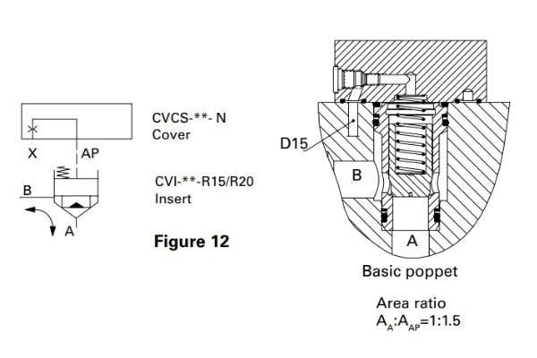
2-Way, 2-Position Function: Sizes 16 to 63
Using a model N cover with a D15 insert, Figure 12, can provide directional control of flow from insert port A to B or from B to A. Pressurizing port X from a remote source will block flow from insert port A and B. With X connected to B, system flow is from A to B. Flow will be from B to A if X is connected to tank or A.
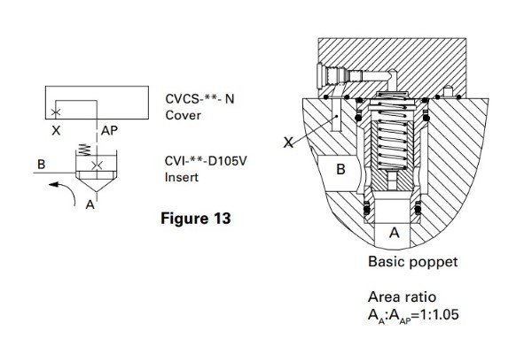
2-Way, 2-Position Function (With Internal Pilot): Sizes 16 to 63
A model N cover is used with a D105 insert (1:1.05 area ratio) which can be supplied with an orifice in the poppet. See Figure 13. This configuration is used to open A to B or block A to B. D105 poppets cannot be used for flow from B to A. The orifice avoids the need to machine a connecting hole in the manifold to port A. To obtain a D105 insert with an orifice in the poppet (i.e. D105V), the orifice size must be specified at the end of the insert model number.
Damping Function: Sizes 16 to 63
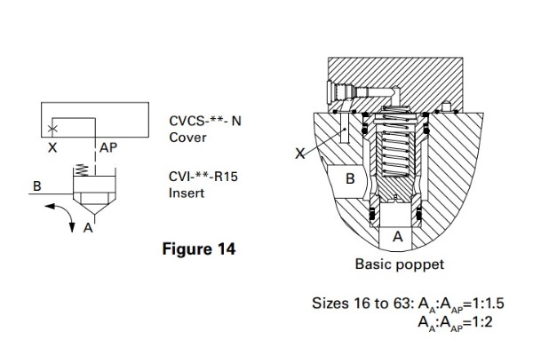
Damping can be achieved with a model R15 insert (area ratio 1:1.5) and R20 (area ratio 1:2), see Figure 14. The poppet has a skirt with a damping notch which helps smooth shifting (reduces gain) of the poppet. R15/R20 inserts may be used with any check or directional function where a D15/D20 insert is ordinarily used.
Pilot Shuttle Control: Sizes 16 to 63
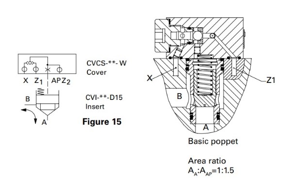
The shuttle function is obtained with a model W cover and D15 insert (Figure 15). The shuttle directs the higher of the pressures at the X and Z1 ports to the spring area (AP) of the insert poppet to close it. The Z2 port can be used as a convenience to operate another cartridge simultaneously.
Pilot Operated Directional Valves
Covers are available with mounting interfaces for pilot valves. These pilots are typically the DG4V-3(S) solenoid operated directional valve that mounts to the ISO 4401, size 03 (ANSI/ B93.7M-D03) interface. Manually operated DG17V-3, pilot operated DG3V-3, or air operated DG18V-3 pilots are also applicable. The Eaton-Vickers soft shift pilot valves DG4V-3-2 can also be used to achieve smooth opening and closing. Single or dual solenoid pilots are applicable (Figure 16), depending on circuit requirements. The spool center condition of the solenoid pilots also depends on the circuit function desired. Ports Z1 and Z2 are for remote control of additional cartridges. That is, for D3 covers, Z1 is connected to pilot port A. The X port is the pilot pressure port. The Y port should always go directly to the reservoir. The insert used can be either the model D15 (1:1.5 area ratio poppet), or model D20 (1:2 area ratio poppet).
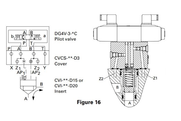
Dual Solenoid Control: Sizes 16 to 63
3-position, spring centered pilot valve
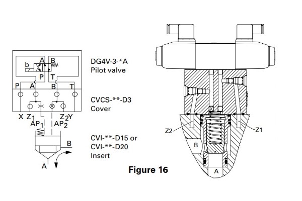
Single Solenoid Control: Sizes 16 to 63
2-position, spring offset pilot valve
Pilot Operated Directional Valves with Shuttle Function
The shuttle function in combination with a solenoid operated pilot valve is available in cartridge sizes 16 through 63. In each cartridge size, the pilot valve is the DG4V-3 that mounts to the ISO 4401, size 03 (ANSI/B93.7M-D03) interface. There are two functional cover types, W13 and W33, that are applied with a model DG4V-3 pilot valve. The insert used can be either the model D15 (1:1.5 area ratio poppet), or model D20 (1:2 area ratio poppet).
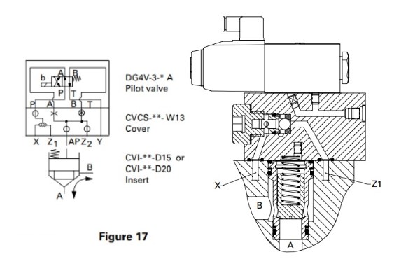
Shuttle Type 1 (W13 Cover): Sizes 16 to 63
With the solenoid de-energized, Figure 17, the cartridge is shut by the higher of the pressures at X or Z1 . Pilot port Z2 can be used to pilot a second cartridge simultaneously.

Shuttle Type 3 (W33 Cover): Sizes 16 to 63
The function of the W33 cover, Figure 18, is to provide a non-reverse flow check, thereby eliminating the need for a separate back flow check. Flow is either blocked or allowed from port B to port A. Flow from port A to port B is always blocked. The application would have pump flow going into port B, port A connected to the actuator and control port X connected to port A.
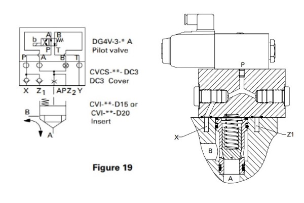
Dual Check (DC3 Cover): Sizes 16 to 63
The DC3 cover, Figure 19, provides parallel check functions in pilot control ports X and Z1. The higher of these two pressures is then available at pilot port P to close the insert via the size 03 solenoid operated valve. A second cartridge can be operated simultaneously from pilot port Z2. The DC3 cover is similar to the type W13 cover but, whereas there is an open transient condition in the shuttle function (type W13), the DC3 design uses two check valves to ensure that no transient loss of pressure in port P can occur during pilot pressure change-over between ports X and Z1. This feature is of benefit in any application where there must be absolutely no risk of the cartridge even momentarily opening during pilot pressure changeover.
Stroke Limiter Control Functions
Flow control is by means of a standard cover with a stroke adjuster which limits the stroke of any of the inserts and thereby limits the flow. Size 16 to 63 The R10 insert (1:1), R15 insert (1:1.5), R20 insert (1:2) has smaller skirt and used as dampening function as well as for fine flow metering (reduced flow gain) during the notch engagement. The F15 insert (1:1.5) & F20 insert (1:2) are the flow control functions with longer skirt and longer notch, hence more notch engagement enabling flow metering over larger stroke.
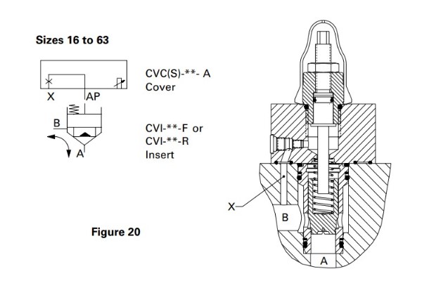
Adjustable Stroke Limiter and Directional Functions: Sizes 16 to 63
The adjustable limiting of the insert poppet opening restricts flow in both directions (A to B and B to A). Control is from pilot port X. See Figure 20.
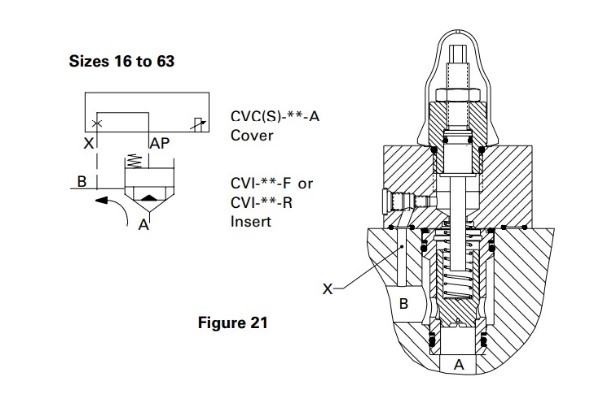
Adjustable Stroke Limiter and Check Functions: Sizes 16 to 63
The adjustable poppet lift limiter restricts flow from A to B. The check function prevents flow from B to A. The X pilot port of the cover is connected to the B port of the insert. See Figure 21.
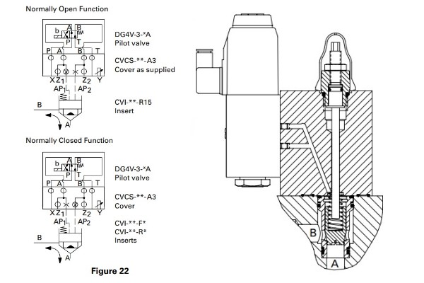
Adjustable Stroke Limiter and Pilot (Directional) Functions: Sizes 16 to 63
Stroke limiters are available with an ISO 4401, size 03 (ANSI/ B93.7M-D03) interface for mounting a single-solenoid controlled DG4V-3(S) pilot valve. These type A3 covers are supplied configured for a “normally open” function, i.e. the insert poppet is vented when the solenoid of the pilot valve is de-energized (with pilot pressure applied to port X). The opposite, “normally closed” (NC) function, can be obtained by interchanging the orifice and plug in ports AP1/AP2. With this arrangement, the insert poppet is “normally closed” (NC) and is open when the solenoid of the pilot valve is energized (with pilot pressure applied to port X).


