Pressure Reducing Functions
The basic pressure reducing cartridge features manual adjustment of reduced pressure plus a pilot port for optional remote control. Additional options include electrical selection of high and low pressure, and electrohydraulic proportional control of reduced pressure. Reducing valve arrangements described in this catalog can be built into system manifold assemblies with directional, manually adjustable flow restrictor and pressure relief functions in cartridge form. The reducing function is available in sizes 16, 25, 32 and 40.
Ratings
Maximum operating Pressure: 350 bar (5000 psi)
Rated flow: p = 12 bar (175 psi)
Size 16: 145 l/min (38 USgpm)
Size 25: 350 l/min (92 USgpm)
Size 32: 630 l/min (145 USgpm)
Size 40: 1025 l/min (225 USgpm)
Pressure adjustment ranges:
- 1.5 to 125 bar (22 to 1800 psi)
- 3.0 to 250 bar (44 to 3600 psi)
- 5.0 to 350 bar (72 to 5000 psi)
All ports are rated up to 350 bar (5000 psi), depending on limits for relevant ports in any associated pilot valves or modules. Note that any pressure in port Y is additive to the setting(s) of the integral pilot pressure control(s).
Pressure Reducing Functions
Unlike other cartridge valve inserts, the reducer insert contains a spool rather than a poppet. Therefore, no reference is made to an area ratio in relation to reducing valves. The reducing valve is normally closed. It varies flow to provide a constant outlet pressure below that of the inlet pressure. The pressure differential between inlet and outlet must be at least 5 bar (72 psi) for optimum reduced pressure control for low flows.
System pressure at B is communicated through a compensated flow control in the X or X3 cover into area AP. This flow control maintains a constant flow across the cover poppet, independent of the main flow from B(P1) to A(P2), thereby providing pressure stability at all system flow rates. Load pressure transients are relieved through the check valve located in the insert spool and are limited by the pilot pressure control in the cover.
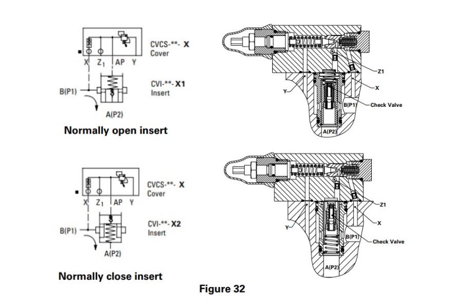
The Z1 port is used for remote control of the reduced pressure. Suitable remote controls are the C-175 and CGR-02. Venting of the Z1 port will cause outlet pressure A(P2) to drop to a minimum pressure related to the spring load in the insert spool. The Z1 port should be blocked when not required. The Y port is used to drain the pilot oil.
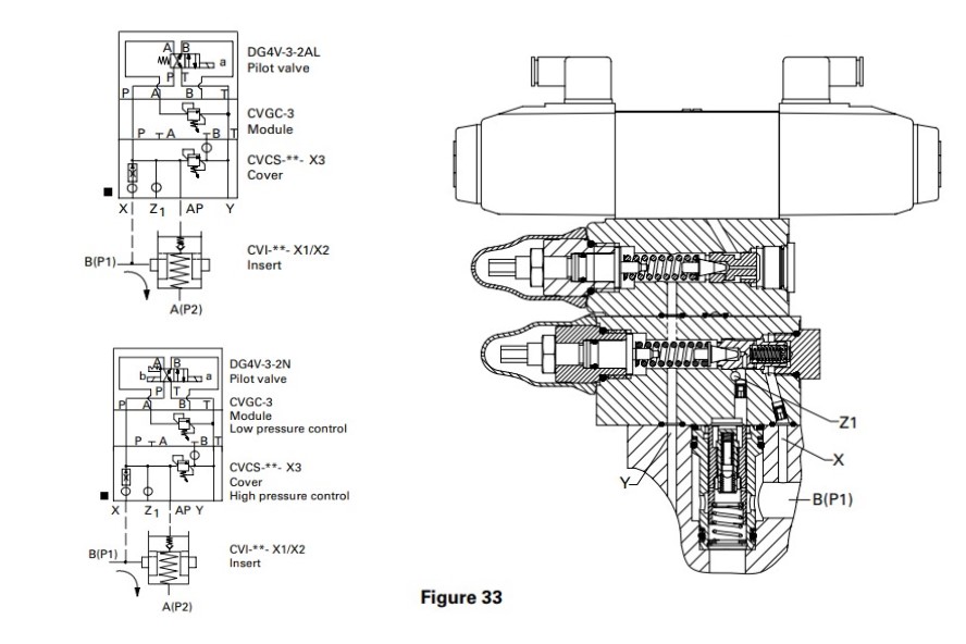
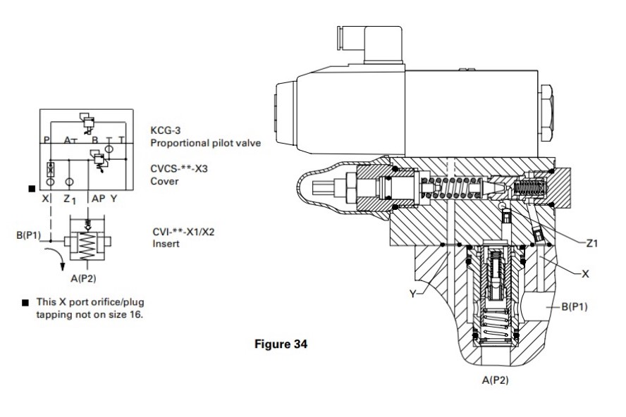
Dual reduced pressure functions are available using the model X3 cover and CVGC-3 module. The X3 cover has a mounting pad with an ISO 4401, size 03 (ANSI/B93.7MD03) interface that accepts pilot valve DG4V-3-2AL (two position, spring offset type) or DG4V-3-2N (two-position mechanical detent type). For information on the DG4V-3 valve. Air operated DG18V-3 or DG17V-3 manually operated pilots are also applicable. An electrically modulated proportional pilot is available that can provide infinitely variable reduced pressure settings and a vent condition.
Cartridge valves for directional and check functions are essentially hydraulically piloted check valves. Control options include single or multiple pilot arrangements, flow restrictors, and solenoid controlled, pilot operated directional control. Grouping cartridge assemblies (selected individually according to flow requirements) for control by one or more common pilot valves can provide directional, check and/or flow restrictor functions for normal flow rates up to 3650 L/min (965 USgpm) per cartridge. Others provide flow restrictions between ports A and B and internal pilot orificing between port A and spring chamber AP. Poppets can be combined with different springs to provide three different cracking pressures.
Pressure Ratings
Maximum pressure allowable at ports A and B is 350 bar (5000 psi) for all cartridges. Minimum pressure is 0,3 to 5 bar (4.4 to 72 psi), dependent on the poppet/spring combination. The maximum pressure limit at pilot ports X, Z1, Z2 and AP and pilot valve interface ports P, T, A and B is generally 350 bar (5000 psi), dependent on the limit of any associated pilot valve or module.
Pilot port Y maximum pressure limit is also 350 bar (5000 psi). However, port Y is normally used as the pilot drain port, when it should be connected directly to the reservoir. In many functions any pressure at port Y is additive to the set opening/cracking pressure of the cartridge.
Remote Pilot Operated Functions
Remote piloted arrangements (pilot not integrally mounted on cartridge cover) require the application of pilot flows and pressures appropriate to the application and within the limits of any associated pilot valves and modules, whichever have the lower limits.
Solenoid Operated, Hydraulically Piloted Arrangements
For full technical data of pilot valves see appropriate Danfoss-Vickers catalog.
Pressure Reducing Functions

Pressure Reducing with Manual Adjustment and Remote Control: Sizes 16 to 40
Reduced pressure at A(P2) is controlled by the manual adjuster in the cover. Pilot port Z1 is used for remote control. See Figure 32.

Dual Level Reduced Pressure by Remote Electrical Selection: Sizes 16 to 40
Alternative arrangements using either the DG4V-3-2AL (two-position, single solenoid, spring-offset) or DG4V-3-2N (double solenoid, two-position detented) pilot valve are shown in Figure 33. Control is at the X3 cover when the DG4V-3-2AL is de-energized or the DG4V-3-2N “b” solenoid is momentarily energized. Control is at the CVGC-3 module, sandwiched between the cover and pilot valve, when the DG4V-3-2AL solenoid “a” is energized or solenoid “a” of the DG4V-3-2N is energized. In each case, the pressure set at the X3 cover should be the higher of the two levels.

Pressure Reducing Function by Electrohydraulic Proportional Control: Sizes 16 to 40
The electrically modulated pilot controls pressure below the maximum manually set level at the X3 cover. Reduced pressure is proportional to the applied current. Increasing current to the pilot increases the reduced pressure at port A(P2). See Figure 34.


